Give your Hexbug a Real Brain!
Chapter 1 – Possibilities –
Hexbug Hack
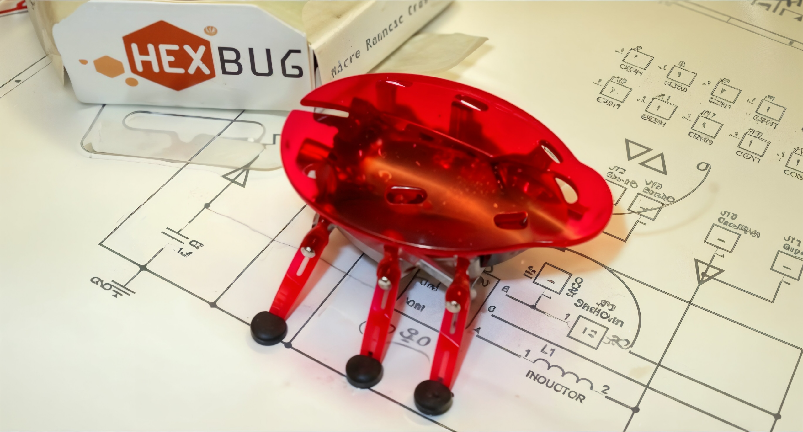
The Hexbug is a very cleverly designed, tiny toy robot bug. Once removed from its package and switched on, it marches forward until its antennae bump an obstacle. It then does a reverse-right turn, and continues forward again until the next obstacle. A loud noise (like a hand clap) will also cause it do its reverse-right turn.
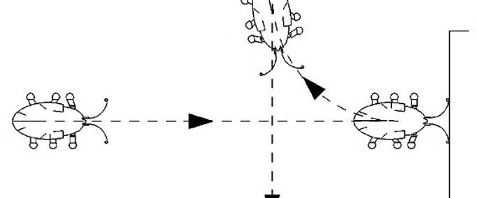
This simple ‘reflex’ response looks very much like a real insect. It does apear like it is exploring its environment. But this is a robotic insect. Shouldn’t robots be smarter?
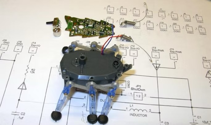
The designers of the Hexbug, Ignition, Inc. and Innovation First, Inc., decided to display the electronics by placing the circuit board on top of the main chassis and under a transparent ‘bug’ shell. This design provides an excellent and easy to use chassis for a much smarter bug. Disassembly is fairly easy, but does require some soldering skills. A new circuit board with a Microchip PIC microcomputer can then replace the stock board and be programmed to match the Bug’s original, simple reflex behavior.
(It might not seem cost effective to add $25 of controller electronics to a $10 robot, but that’s the wrong perspective- How about building a $25 robot controller board and being able to get a $10 pre-built robot chassis for it?)
Now the real fun begins. Even though the Hexbug’s motion is limited, with the addition of a few simple sensors and some clever programming, it can do remarkable things. For example, a right turn (the only direction the Bug can turn) is accomplished by doing a reverse turn for about 2 seconds. How can it make a left turn? Simply do a right turn for 6 seconds – 3 right turns equal one left turn.
(Solving these types of problems- finding functional solutions using very limited resources- are the sort of challenges NASA has had to face when thing go wrong with distant space craft. The only thing that can be done to solve the problem is to upload new control software.)
With these small additions, the Bug can now be programmed with new, additional behaviors. Some possibilities:
The Bug could periodically ‘sleep’ instead of just marching along, avoiding obstacles until it’s switched off. While the microcomputer is in ‘SLEEP’ mode, almost no power is used. The Bug could be active for 30 second, and then sleep for 2 minutes. The Wake/Sleep periods could be made random to give it behaviors closer to a real ‘bug’.
The Bug could be given programming to use a piezo-buzzer to make sounds as it explores. This would definitely give it a ‘Personality. (What would Scrat be without all his funny sounds?)
The Bug could be programmed with a musical scale and could ‘sing’ for special occasions: Happy Birthday, We Wish You A Merry Christmas, Who Let The ‘Bugs’ Out….
The Bug could monitor its own battery voltage, and ‘Cry’ for new batteries when its power gets low.
The Bug could be given a light detector, and be programmed to seek the brightest place in its environment.
The Bug could ‘go to sleep’ when it’s dark, and be randomly active when it is light.
The Bug could be equipped with rechargeable batteries and solar cells. With a light detector modification, it would look for a bright place to recharge when it detects its batteries are getting low.
The Bug could be equipped with an IR-control module and programming to read the signals from a TV remote. This could provide direct remote control, or a means to remotely program a ‘behavior’ (explore/march/dance) into it.
The Bug could be programmed to seek out a ‘charging station’ that uses an IR transmitter similar to the TV remote to park and recharge its batteries.
The Bug could be equipped with a microphone and tone decoder and software so it could be controlled using a tone generator, and could also ‘talk’ to other Bugs with the same type programming.
The Bug could be equipped with IR Proximity sensors to detect the edge of the desk/table it’s walking on. Two would be needed: center front and rear-left. There is the chance that the Bug could walk up to a corner, with the edge of the desk/table on its left. A left-reverse turn would but it over the edge. It would have to detect this condition, and then ‘cry’ for help.
The Bug could be equipped with an Electronic Compass for navigation. (Distance traveled would still be ‘open loop’.)
Give your Hexbug a Real Brain!
Chapter 2 – What’s Inside –
As observed earlier, the Hexbug has just three functions when turned on- Forward, Reverse turn upon bumping its antennae, and Reverse turn after a loud sound. ( There is no Pause, or Stop ) The microphone and the antennae on the PC board are easily observable, but what’s inside? If you gently try to move the legs, you find that the right legs are locked, but the left set can be moved. These are also the legs that stops moving when the bug makes its reverse-right turn. This indicates that some sort of a clutch must be driving this side. Opening the battery compartment reveals two L1142 batteries. These are alkaline batteries rated at 1.5v, 105mahr at a drain of .25ma., and indicate that the system runs at 3 volts and under. (Typically, the useful life of a standard alkaline battery is considered over when its voltage drops to .9 volts. After this, the voltage drops rapidly- .8 volts is the “gooey-ooze” stage. This means the system can run on a supply voltage as low as 1.8 volts.) A single screw near the antennae can be seen through the transparent shell. It is the only one, and holds the PC board to the chassis, and the front of the two halves together. At the back of the bug body, there is a small rectangular cut out with a tab in it. This holds the back halves of the chassis together.
But to learn more, we need to open the bug up…
The first step in opening the Bug, is to remove the transparent plastic shell. It is connected to the chassis by seven press fit pins. They can be freed, one at a time, by wedging an X-Acto knife or other sharp, thin edge into the crack between the chassis and shell posts. A little wiggling should pop each free. Removing the small screw near the antennae will allow the chassis to be opened. Do this carefully if you want to look inside- You do NOT want to dump out all the small gears and clutch parts!
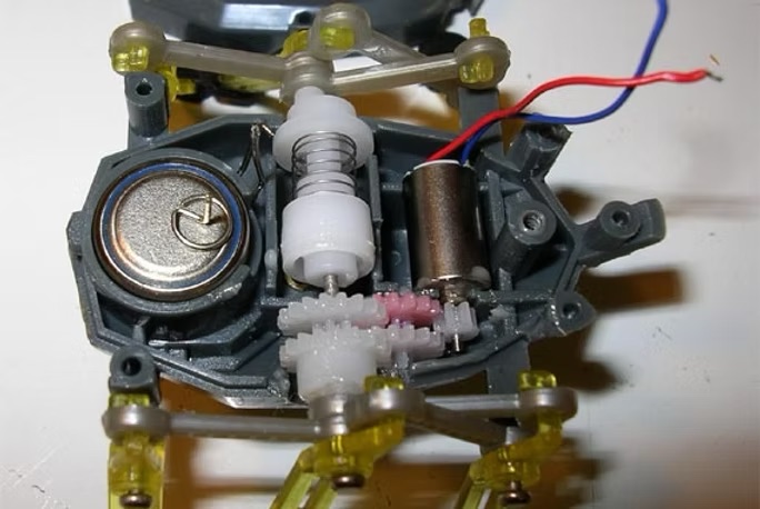
Gear train, motor, clutch, battery and battery contacts
If you can curb your curiosity, and be satisfied with the pictures, don’t open it. Strap the two halves together with a piece of wire that held the Bug in its package.
Inside of Spiral-ramp clutch
There are four electrical connections between the chassis and the PC board. Two stiff battery contact wires pass through the chassis from the battery compartment and provide power to the PC board. These must be unsoldered first, using either a solder-sucker or de-soldering braid. (To prevent accidentally shorting the batteries during unsoldering, take them out, and insulate the top contact from the battery with a small piece of paper, Not plastic- the heat of unsoldering could melt it. Re-install the batteries. This will make re-assembly easier by preventing the contact wires from shifting/falling out after they are unsoldered.)
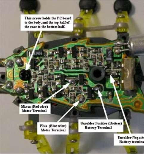
Electrical connections
The last two connections are the red and blue flexible wires from the motor. These are more easily removed after the PC board is removed.
With the two halves of the chassis strapped together, remove the small screw, and gently pry/wiggle the board off the central post. Apply the soldering iron to the motor wire connections on the top side and lift the board as the chassis pulls away. Repeat this for the other wire, and then replace the screw to hold things together. (And so the screw doesn’t get lost!)
Next, the antennae need to be salvaged. The antennae are very well designed. They are actually two pieces- the outer spring wire, and a partially insulated center post. Unsolder the spring wire first using either the solder-sucker or de-soldering braid, and then the post. Note that there is a right and left antenna. This will be important when re-assembling them on a new circuit board.
Now we have a robot bug chassis ready for a new brain!
Give your Hexbug a Real Brain!
Chapter 3 – Controller Design – New Brains –
The new controller will need to replace the functions of the original board:
Motor control- Forward and Reverse
Detection of obstacles- Antennae
(No microphone- for reasons that will become clear later.)
And will add:
Motor Off
Piezo-buzzer
Blinkable ‘Eye’
Low battery detection
Light level detection
To implement this, the first item needed will be an 8 pin, Microchip PIC microcomputer. The PIC series can run on voltages as low as 2 volts, and use less than 1 micro-amp in sleep mode. (Microchip provides excellent support and Application Notes for the PIC chips, and provides a free compiler/debugger, as well as inexpensive programming modules- More on this later.) Next, we need an H-bridge to control the motor, the original antennae, an LED, a piezo-buzzer, and a voltage reference.
But where is the light level detector? Here we use the LED in two different ways- as both a light source, and light detector. This works because the I/O pins on the PIC chip can be reprogrammed on-the-fly, and this ability will be very useful in implementing the rest of these functions.
So, how many control pins from the microcontroller do we need? To be able to fully control the H-bridge we need 4 pins. The antennae will need 1 pin, and the LED 1 pin. The piezo-buzzer 1 pin, and voltage reference 1 pin, but here we have two complications.
1) The piezo-buzzer will not be very loud at the low 3 to 1.8 supply voltage. This can be doubled to a peak-to-peak voltage twice that (6 to 3.6 volts) by driving it differentially from 2 pins.
2) The voltage reference will need an additional pin to turn it on and off to conserve power.
This gives us a total requirement of 10 pins. Oh, we also need power and ground- that’s 12 pins. We only have 8, and it would be nice to have some available for future expansion. We need to re-use pins.
Let’s start with the H-bridge. Four pins will give us 16 possible combinations, or states:
H-bridge States |
|
|
|
|
| ||
|
|
|
|
|
|
|
|
State # | Pin ‘A’ | Pin ‘B’ | Pin ‘C’ | Pin ‘D’ |
| Motor Function |
|
|
|
|
|
|
|
|
|
0 | 0 | 0 | 0 | 0 |
| – OFF – |
|
1 | 1 | 0 | 0 | 0 |
| – OFF – |
|
2 | 0 | 1 | 0 | 0 |
| Short Circuit A->B |
|
3 | 1 | 1 | 0 | 0 |
| Reverse | <<< |
4 | 0 | 0 | 1 | 0 |
| – OFF – |
|
5 | 1 | 0 | 1 | 0 |
| – OFF – (All MOSFETs OFF) | <<< |
6 | 0 | 1 | 1 | 0 |
| Short Circuit A->B |
|
7 | 1 | 1 | 1 | 0 |
| – OFF – |
|
8 | 0 | 0 | 0 | 1 |
| Short Circuit C->D |
|
9 | 1 | 0 | 0 | 1 |
| Short Circuit C->D |
|
10 | 0 | 1 | 0 | 1 |
| Short Circuit A->B,C->D |
|
11 | 1 | 1 | 0 | 1 |
| Short Circuit C->D |
|
12 | 0 | 0 | 1 | 1 |
| Forward | <<< |
13 | 1 | 0 | 1 | 1 |
| – OFF – |
|
14 | 0 | 1 | 1 | 1 |
| Short Circuit A->B |
|
15 | 1 | 1 | 1 | 1 |
| – OFF – |
|
|
|
|
|
|
|
| |
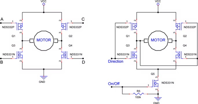
H-Bridge and Cross-wired Bridge with On/Off Switch
We only need three states- Forward, Reverses and Off.
Cross wiring the bridge will require only 1 pin instead of 4, giving 2 states, Forward and Reverse. One complication with this configuration is ‘shoot-thru’- as the MOSFETs change state, both the ‘P’ and ‘N’ are momentarily on at the same time, and a large amount of current ‘shoots thru’. If one more MOSFET is added, the H-bridge can be switched On and Off, giving us the Off state, and shoot-thru can be prevented if we are careful to turn the bride off before we change direction. The On/Off control line needs to be dedicated, however, or re-using it could turn the motor on when it’s not needed.
Now we’re down to 10 pins.
One pin can be used to power the LED and drive one side of the piezo-buzzer. By re-configuring that pin to use the PIC’s A/D converter, it can read the voltage reference or the LED’s voltage when it’s working as a photocell. ( Yes, an un-powered LED is a photocell; any diode is a photocell. If a discharged capacitor is placed in parallel with an LED, the LED will convert photons to electrons, and start charging the capacitor. The more photons the LED picks up (brighter light source), the more electrons, and the faster the voltage on the capacitor rises. By measuring the voltage after a set time period, the light level can be determined.) Another pin is assigned to power the voltage reference, and can also be used to power-on future expansion modules. One more pin is needed to power the other side of the piezo-buzzer, and can also be used for future expansion- if the piezo-buzzer’s other leg is connected to a pin that the PIC chip turned off (set as a high impedance input), it can be re-used as a digital In, Out, or Analog In. (In most cases, it doesn’t matter what the other leg of the piezo-buzzer is connected to, as it will appear as a small capacitor.)
So, here are the pins we really need:
| 1: Motor On/Off 2: Motor Direction 3: Antennae 4: LED, Piezo & Volt-Ref. 5: Power Volt-Ref. & Expansion 6: Piezo & Expansion | Dedicated Digital Output Function Digital Output; Can be re-used Digital Input – input only pin Digital Output & Analog In Digital Output; Can be re-used Digital Output; Can be re-used |
And, we still have two pins left for power and ground.
For the 8 pin PIC chip used for this upgrade, pins 1 and 8 are assigned to power and ground, respectively.
Pin 4 is input only, and must be available for programming, so this is a good choice for the antennae. Pins 7 and 6 are used for the In-Circuit-Serial-Programming (ICSP) function, and must not be loaded with a capacitance (the piezo-buzzer) or a low resistance. Pin 7 will be connected to the dedicated motor on/off signal, as the gate of the MOSFET has very high impedance, and will not interfere with programming, and pin 5 as the motor direction control. Pin 6 is assigned to drive the piezo-buzzer, but will have to be switched between the ICSP programming function, and driving the piezo. Pin 2 is assigned to powering the voltage reference and external expansions, and Pin 3 is assigned to the LED, piezo and voltage reference.
Pin-1Vdd- Power
Pin-2GP5- Voltage reference & expansion power
Pin-3GP4- LED, voltage reference, Piezo-buzzer
Pin-4MCLR, GP3- Antennae
Pin-5GP4- Motor Direction
Pin-6ICSPCLK, GP1- Piezo-buzzer
Pin-7ICSPDAT, GP0- Motor On/Off
Pin-8Vss- Ground
Because the motor is a brushed DC motor, it can produce inductive voltage spikes on the power buss that could disrupt the PIC’s operation. This is easily remedied by placing a filter inductor between the PIC’s power buss and the motor’s.
Resistors are also needed to keep the H-bridge in the ‘Off’ state while the PIC is in sleep mode.
Also needed are connector pins for programming, switching of the dedicated programming pins, and a means to turn power off. This can be solved by bringing these signals out to a row of header pins at the back of the board. A jumper block can be used to switch power and the programming pins used for operational mode. Another header can be used to both connect a programming cable, and also disconnect the battery, and power to the motor.
Now a schematic can be created, and a printed circuit board can be laid out.

(Click image to enlarge)
– The Great Revision – HXB27e
The Improved Hexbug PC board – After building several upgraded Hexbug’s using the HXB14c PC board, and doing various experiments and evaluations, I realized that a few modifications and adjustments to the original design could make it even more versatile. So, after further analysis, the following modifications and features where added to the original HXB14c printed circuit design:
1) Minimize any changes that would make the new board incompatible with the original HXB14c design and its software.
2) Layout the PC board to allow the use of either a surface mount SOP or leaded DIP package. This enables lowering the Bug’s shell to the original height with the SOP, but will make replacing the PIC much more difficult. The mounting holes for the DIP have been slightly enlarged to allow the use of individual, flush sitting, socket pins instead of a standard, above board socket. This also allows the shell to be lowered.
3) Allow the use of either or both surface mount and leaded capacitors, and use only the ‘larger’ (right… .120x .060 inches is large) surface mount components to make hand soldering a bit easier.
4) Using just the one (Cyclops eye) LED light detector complicated tracking the direction to the brightest light. Providing placement for two LEDs improves this, and looks more like ‘Eyes’.
5) Move the ZXRE4041’s output to the ADC Vref input pin. (This is the only significant change to the software configuration due to the hardware changes. Pads for an additional surface mount resistor to use the same configuration as the HXB14c board have been provided.)
Why move it?
6) The LED light detector configuration used the 10-bit ADC with the supply voltage as its reference voltage. With fairly new batteries providing a full scale voltage reference of 3.0 volts, 1 bit equals 3.0/1024= 3mv. This does not allow very good discrimination of different low light levels. If the ADC is supplied with a lower voltage, external reference (via the pin 6 Vref), one bit now equals 1.225/1024= 1.2mv per bit- better than double the discrimination. (There may be other advantageous uses for this configuration.)
7) If instead of turning the Vref on with one pin and reading it through another, a capacitor is placed in parallel with it, then only one pin is needed. (This means more flexibility for further expansion) This one pin first charges the capacitor to the reference voltage, then is reconfigured to read it. Though some careful analysis must be done first, the results are very stable and repeatable. The voltage on the capacitor does slowly decay, but at a rate of 30mv/sec (measured), and with an A/D conversion rate of 45µsec, a lot of conversions can be done before there is a significant change in accuracy. This can even be used to advantage to improve the sensitivity of the LEDs as photo detectors. If the capacitor voltage decays at a known rate, the software can delay reading the ADC until the voltage is lower. This results in more bits per millivolt.
8) Although the IR receiver module could be mounted anywhere, and wired to the PC board (this is still an option), mounting holes have been provided to mount it directly on to the PC board.
9) The option of using the header-jumper to switch power, or install the Bug’s original miniature switch to turn it on and off is now avalible. If you wanted to preprogram the Bug as a gift or presentation prize, a non-technical recipient would be less confused by a standard switch as compared to the jumper.
10) Easier mounting of the filter inductor, L1. The original layout required the leads to be scrunched-in to fit onto the PC board.
11) A capacitor has been added across the motor terminals to reduce electrical noise and add protection for the MOSFETs from inductive spikes.
These modifications required moving most of the parts, so the new HXB27e board has a new parts layout diagram. It uses the same parts, and is tolerant of variations on some of these. The resistor that limits current to the piezo and LEDs can vary from 150 ohms to 1K. Larger values will save power, but give softer sound, and dimmer LED’s. Smaller values will reverse these effects. The values chosen are a good compromise.
Assembly is basically the same as the original HXB14c. The only changes are the addition of several new components.
NEW HXB27e Schematic
Why no Microphone?
Duplicating the current ‘clap to turn’ function of the original board adds limited functionality, and increases power consumption.To be really useful, the input from the microphone should be processed to convey more information than just the detection of a loud noise. (We are trying to build an autonomous Robot, not replace ‘The Clapper’.) A more useful sound detection system would use a phase-locked-loop (PPL) to detect specific tones, and use these as command inputs. By using an IR receiver module, and a TV remote control, a simpler, lower power method for remote control and programming can be implemented.A more complex sound control/communication system could be created, but would use more power, and would best be implemented as a separate module that could be turned off to conserve power when not needed, or in ‘Sleep’ mode.Besides, it is more entertaining to have the Bug do all the talking.
Give your Hexbug a Real Brain!
Chapter 4 – Assembly –
Although the new controller can be built on a pad-per-hole prototyping board, using a printed circuit board will be much more convenient. A double-sided, plated through hole and solder masked board can be obtained from Applied Inspirations, LLC.

The last components to get soldered to the PC board should be the antennae (due to there fragility and to prevent the insulator between the post and the spring from being distorted during surface mount soldering.) The first components to be mounted on the PC board are the surface mount parts. (Make sure the surface mount parts are soldered before the piezo-buzzer; it installs over the H-bridge.) Only the resistors and MOSFETs are surface mount components for several reasons:
1) Surface mount ceramic capacitors should NOT be soldered by hand, one contact at a time. They tend to crack or short internally and fail. Or worse- they may be slightly damaged and fail intermittently. Intermittent problems are the most difficult to debug.
2) The PIC chip is socketed so that different chip versions can be used, it can be replaced if damaged, and so it can be programmed externally, and then plugged into the board. If external programming is used, the connector pins and jumper can then be eliminated, and a simple switch used to turn the bug on and off.
3) An axial leaded filter choke is less expensive and smaller than its equivalent surface mount package.
4) Resistors and SOT-23 MOSFETs have enough flex in their packaging to prevent damage when hand soldered.
NEW HXB27e Parts List:
( The Assembly sequence is basicly the same )
NOTE: Most of these parts can also be obtained from Digikey and other suppliers.Resistors, capacitors, the zener, and LEDs can be easily substituted for, however,Do Not substitute Parts in BOLD BLUE without careful evaluation for equivalence.

NOTE: These are the original, HXB14c, Exploded Assembly Sequence and Parts List.They will be updated in the future and archived in a reference section that will be maintained for all early project versions.


(NOTE : The MOSFETs used here, NDS331N and NDS332P, are special Low Gate Voltage parts. If other MOSFETs are substituted, make sure their turn-on gate voltage is low enough. )
The surface mount devices (SMDs) can be hand soldered, one at a time, with fine solder and a fine tipped, low power soldering iron- preferably temperature controlled. (Use anti-static precautions, and install the resistors first to help protect the MOSFETs’ gates.) I did my first surface mount projects this way, until I discovered what sadly seems to be:
The ‘best kept secret’ of surface-mount prototype assembly-
I met Dave Jacks, president and founder of Zephytronics at the ’06 NEPCON show. (I almost left early and would have missed him.) He was demonstrating Zephyrtronics’ line of surface mount repair and prototyping equipment. My eye’s got wider as he deftly demonstrated soldering and unsoldering finely pitched, 44 pin chips from a PC board as quickly as one of those “never needs sharpening” knife demos, where they cut a tomatoes into fifty, paper thin slices in the blink of an eye. Only, this was not snake oil!
The commercial way of assembling surface mount components is to screen print solder past onto the PC board, place all the components with a high speed automated placement machine, and then run the board through a controlled temperature-cycle oven.
Though the solder paste and components can be placed by hand, and boards have been soldered in toaster ovens, the biggest problem is the solder past itself- it must be shipped cold, and if not refrigerated, the solder and flux will separate, and harden up.
If you are willing to live with this, Digikey has it- a 100gr syringe is about $57, and must be shipped overnight express; more $$$.
A Better Way
There is however, a better way- Zephytronics has pioneered a solder paste that does not need to be refrigerated. They have developed a solder paste that is stable, on the bench for six months, and much longer if refrigerated. I’m almost out of my first tube I bought two years ago, and it’s still good. When not being used, I keep it in one of those tiny, dorm-room type refrigerators. A 10cc syringe is about $15, and they have no minimums.
Their website has a great deal of very good ‘how-to’ as well as technical information about surface mount soldering (http://www.zeph.com/pap1.html). They sell some excellent equipment, though it’s a bit pricey for hobbyists.
For occasional / limited surface mount soldering, a good, digitally controlled heat-gun will work. The best deal I’ve found is the one offered by Ace Hardware, and it’s under $35 if ordered over the web. Additionally, a thermocouple temperature probe should be used to monitor the air and board temperature. Some good digital multimeters include them.
There will be more information on surface mount soldering on this website laterThe surface mount soldering section is still under construction.
NEW HXB27e Parts Placment:

HXB27e-PrtsPlcmnt-Web
1/1
(Click Image for Detailed .PDF Diagram)
NOTE: This is the original, HXB14c, Parts Layout.It will be archived in a reference section that will be maintained for all early project versions.
The basics of this assembly method are:
1) Spot apply solder paste to all the surface-mount pads.
2) Place the components, and align them with the pads. (In most cases, if the pad geometry is correct, the surface tension of the liquid solder will pull the parts into alignment, but they need to be close.)
3) Place the board in a semi-enclosed area (sheet metal or plasterboard are two good possibilities) to help direct the hot air from the heat-gun to the board’s underside. Place the tip of the temperature probe so it’s pressed against the top of the board.
4) Over about a minute’s time, slowly ramp up the temperature to 300°F. Let the board ‘soak’ at this temperature for about a minute. The board and components can safely be left at this temperature for extended periods of time. The flux component of the solder paste will cause it to first flow, and then will dry out.
5) Raise the air temperature to about 430°F quickly and carefully watch for the solder to flow. As soon as the solder has flowed on all the pins, quickly reduce the air temperature, and let it cool back to room temperature with just air.
After the surface mount parts have been soldered, install the capacitors, piezo-buzzer, inductor, and the 8-pin header (or jumpers) and 8-pin socket. The leads of the LED should be insulated and bent to place it between the antennae. It should also be inserted from the BOTTOM of the board if the transparent bug shell will be replaced. Finally, install and solder the antennae to the BOTTOM side of the board. Note that there are right and left antennae!
To be able to program the PIC chip in circuit, and test the Bug’s performance, a programming cable will be needed. This can be wired up using an 8-pin female header for the Bug side, and a 5-pin male header for the PICkit-2 side. (Other Microchip and third party programmers will work also, but may have different pin-outs and/or external power requirements.)

Before the new board is installed on the Bug chassis, it should be tested- It’s a bit of a pain to unsolder it from the battery terminal wires once it’s installed. And before it can be tested, we need a control program.
Just for reference, as the board can not be tested without software:
The final assembly is done by first soldering the motor leads to the controller (but NOT the battery connections), applying power and verifying system functionality, particularly that the motor is running the right way. (If it does get wired in backwards, the solution would be to reverse the software definition of forward and reverse. But we don’t make those kinds of mistakes, now do we?) The screw holding the chassis halves together is removed, and the board is placed on the chassis, lining up the battery pins with the PC holes. Reinstall the screw and solder the battery pins.
Give your Hexbug a Real Brain!
Chapter 5 – Control Software –
As mentioned earlier, the PIC microcontroller chip was chosen for this project because of the excellent support, availability, and low cost from Microchip. Microchip also provides a free software development package for it called MPLAB. (It’s truly FREE, not just for 30 or 60 days as some companies’ evaluation packages are.) Both the program and user’s guide can be downloaded from their site. You will have to buy the programmer though.
Any one of these tools will be suitable for programming the bug. They are a very good value for the money. (There are also third party suppliers of programmers.)
| Current as of 3/23/10 | ||||
| Tools- | ||||
| From Microchip Direct, Mouser, and Digikey: | ||||
| DV164120 | PICkit-2 Starter Kit | $49.99 | ||
| PG164120 | PICkit-2 Programmer Only | $34.99 | ||
| DV164101 | PICkit-1 8/14P Flash Starter Kit | $36.00 | ||
| DV164121 | PICkit-2 Debug Express | $49.99 | ||
| All these packages include the MPLAB IDE software CD. | ||||
My personal recommendation is the PICkit-2 Starter Kit. Besides the programmer module and MPLAB software, the kit includes a demo PC board with a PIC16F690 chip, A series of 12 Lessons on assembly programming including source files, and a HI-TECH PICC™ LITE ‘C’ Compiler. With the additional software provided, the programmer module can also be used to analyze serial communications and as a three channel logic analyzer.
More information about MPLAB can be found on the right..
More information about the PICkit-2 can be found on the right.
If you are not familiar with the PIC assembly language and would like to get started, there is a good, free online tutorial, “PIC Assembly Language for the Complete Beginner” by Michael A. Covington at: http://www.covingtoninnovations.com/noppp/picassem2004.pdf
Why write in assembly language? Freedom. Though you have to handle all the details yourself, once they are set up, you can “have it your way”. Basic, C, and other high level languages do take care of a lot of details for you, but in relatively simple projects, there aren’t that many inter-connected details that need it.
Using assembly language with PIC chips is more like ‘writing hardware’. The PIC’s instruction set is made of a few (35) small, fast efficient instructions out of which bigger function can be made. These then can be re-used. It’s a little like creating your own ‘higher level’ project-specific language.
This implementation uses the PICkit-2 programming module. As this is a first/test version, the software for the Bug is very basic, and does not use interrupts so they are disabled in the initialization routine. Future versions may use them- this is just a starting point. The code is broken up into several sections- Initialization, Subroutines, and Behavior.
(If you create a new, or modified program and Bug behavior, please e-mail it and its ‘personality’ description so it can be posted for others to try. If you wish, your contact information will be posted with it)
Initialization Details-
To conserve power, the A/D converter and other analog functions are disabled. If the ANSEL (Analog-Select) register is not cleared, ports GP0,1,2 & 4 will be in analog input mode, and will read digitally as a ‘0’. The watchdog timer is enabled to provide its maximum timeout of 2.3 seconds. By using the internal oscillator two pins are freed up. It runs at 4 mhz. The master clear pin (MCLR) is assigned to be used as a digital input, and here is a tricky detail that can be easily over looked when also using the ICSP function.( See- http://support2.microchip.com/
KBSearch/KB_StdProb.aspx?ID=SQ6UJ9A003LD4 on microchip’s website for more details.)
The MCLR pin is used by the PICkit-2 to start the programming cycle. When the chip is programmed for the first time, the MCLR pin will be in the default master clear mode. On the next programming cycle, the previously installed initialization routine reprograms the pin as a digital input before the PICkit-2 programmer can put it into programming mode. The programming cycle will fail, and it might appear that the chip is bad. The only way out of this problem is to erase the whole chip, then reprogram it. You did remember to read and save internal clock’s factory calibration value didn’t you?
There is another way around this problem. A small delay is inserted into the code before the initialization routines are run. This will allow the PICkit-2 to gain control of the MCLR pin before it can be changed.
Subroutines-
With the initialization details completed, the next elements needed are the subroutines. Some of these are made from lower level ones. Their details can be found in the assembly code listing, so the following is a simplified list of the major ones, and their functionality:
| Sound Effect Sub.s; When called, they configure and use the piezo-buzzer- | ||
| UhOh1 | Sounds like- “Uh-Oh” | |
| OhOhOh | Distress | |
| OhUh1 | Sounds like- “OK?” | |
| Trlla | Trill-A | |
| Trllb | Trill-B | |
| Trllup | Sweep Trill-Up | |
| Trlldwn | Sweep Trill-Down | |
| Chips1 | Seven, quick, short “Chip” sounds | |
| Chips2 | Twenty, quick, short “Chip” sounds | |
| BEEP | 256 Cycles at Freq. set in ‘TONE’; duration passed in ‘W’. Base for all tones. BEEP turns ON needed I/O, then turns it OFF when done. | |
| Motor Sub.s; These configure the ports, and delay the On/Off switch to prevent ‘shoot-thru’- | ||
| Fwrd | Motor ON, Forward | |
| Rvrs | Motor ON, Reverse | |
| STOP | Motor OFF, Forward | |
| Utillity Sub.s | ||
| BattStat | Returns battery status value in ADRESH, & ADRESL by reading the voltage reference value using the 10 bit A/D converter. The A/D converter’s reference voltage is the supply voltage. As battery voltage drops, the voltage reference chip’s value appears to rise. Sets up the ADC using Vcc as reference voltage. Turns on Vref (GP0), and measures AN-1. If Vcc is 2.5VDC, then 1.22 Vref will read as 47.84% of the ADC. With a Max count of 1024, 490 = Vcc = 2.5vdc. At a min battery voltage of 2.2, the ADC would read Vref as 568. | |
| PhotoStat | Read LED used as solar cell, Returns Value in ‘W’- operation is similar to BattStat | |
| PwrDwn | Puts PIC into lowest power state before sleep. | |
| Delays; The delay count is passed in ‘W’ register. It must be set befoer calling these subs- | ||
| DLY_S | 10uSec per count | |
| DLY_L | 2.5mSec per count | |
| DLY_X | 100mSec per count | |
| Output- | ||
| DeciDig | Convert value passed in variable ‘OutByt’ to 3 Decimal Digits and output as 3 sets of beeps. If Zero, sound 1 low tone, else sound a high tone beep to equal the count. This routine can be used to output the BattStat value | |
The details of these subroutines can be found in the assembly code listing.
[Click HERE to down load the basic assembly code .DOC of .ASM file]
[Click HERE to down load the basic assembly code .DOC of .HEX file]
Main Code: Test & Personality-
Now for the main ‘personality’ code- For this version, the first thing the Bug should do is test its systems. These should not start until we want them to, so the first part will be to blink the LED and wait for the antennae to be touched. It will then make some sounds, turn the LED On then Off, run the motors forward, reverse and forward again, turn the LED On then Off again, output its battery voltage level as a series of tones, and go back to blinking the LED and waiting for the antennae to be touched. Here is a sample of the code; ( Note that by having created subroutines first, 23 of the 36 instructions are either a subroutine call, or a ‘MOV’e the Literal value into the ‘W’orking register,”MOVLW” )
| Test: | ||||
| Configure I/O | ||||
| BSF MOVLW MOVWF BCF | STATUS,RP0 b’11001000′ TRISIO STATUS,RP0 | ; Set Bank 1 <<–+–### ;Init. I/O- Motor, LED/Vref PWR, Piezo ; Set Port A I/O: 1= Input, 0= Output ; Set Bank 0 <<–+–### | ||
| Wait for Antennae bump | ||||
| TstLp1: | ||||
| MOVLW CALL BSF MOVLW CALL BCF BTFSC | d’10 ‘DLY_X GPIO,1 d’2′ DLY_L GPIO,1 GPIO,3 | ;Wait 1 sec ;100ms/Cycle ;LED On ;Wait 100 msec ;@ 2.5mS per count = 5ms ;LED Off ;Loop until Antennae is touched.. | ||
| GOTO | TstLp1 | |||
| Test Sounds | ||||
| CALL MOVLW CALL CALL MOVLW CALL | Trlldwn d’10’ DLY_X Trllup d’10’ DLY_X | ;Down-Sweep Trill ;Wait 1 sec ;100ms/Cycle ; -Sweep Trill ;Wait 1 sec ;100ms/Cycle | ||
| Test Battery | ||||
| ;Read Battery Voltage level- | ||||
| CALL MOVF MOVWF | BattStat ADRESH,W OutByt | ;Get voltage level ;Save for conversion… | ||
| ;Convert value passed in ‘OutByt’ to 3 Decimal Digits: | ||||
| CALL MOVLW CALL | DeciDig d’10’ DLY_X | ;Output value as ‘Beeps’ ;Wait 1 sec ;100ms/Cycle | ||
| ;Signal end of testing | ||||
| CALL CALL MOVLW CALL | Note_G2 Note_E2 d’10’ DLY_X | ;Wait 1 sec | ||
| Wait for Antennae bump | ||||
| OprLP: | ||||
| MOVLW CALL BSF MOVLW CALL BCF BTFSC | d’10’ DLY_X GPIO,1 d’2′ DLY_L GPIO,1 GPIO,3 | ;Wait 1 sec ;100ms/Cycle ;LED On ;Wait .1 sec ;@ 2.5mS per count = 5ms ;LED Off ;Loop until Antennae is touched.. | ||
| GOTO | OprLP | |||
| Personality Program Goes Here | ||||
PERSONALITY-1:
The next block of code is the bugs ‘personality’. Look through the code listing for more details. Here is a basic outline:
Main Loop>>
Start walking, start timer
If Antenna bump-
Stop; Count bumps; after 5th bump, complain
Reverse turn;
After 10 bumps, throw a ‘tantrum’-
Move back and forth with sounds;
Sleep for 5 seconds
If no bumps occur for 30sec, celebrate-
Reverse circle with sounds
Sleep for 10 seconds
Wake; reset counters;
Go back to Main Loop-
Some simple additions coming in the near future:
1) Monitor the battery voltage and have the Bug ‘cry’ when its batteries get low.
2) Have the bug respond to light levels- The PIC chip could be put into lowest power ‘Sleep’ mode and would be awakened by the Watch Dog Timer (WDT). If the light level was high enough, the bug would start wandering around. When the light level dropped, the bug could go back into ‘Sleep’ mode.
Give your Hexbug a Real Brain!
Chapter 6 – Testing, Programming & Final Assembly –

SETUP-
(NOTE: This section assumes that you have some knowledge and experience using MPLAB and using the PICkit-2/1 to program chips.)
‘SMOKE-TEST’-
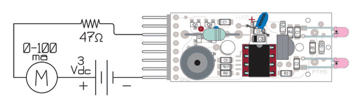
First power-up connections- The ‘Smoke-Test’
Connect a 0-100 milliamp meter in series with a 3 volt DC supply and connect the negative side to the header’s ground pin.
Apply power to the VinL pin through a 47Ω resistor. (This will limit the current to a max. of about 64ma., preventing damage even if something is in backwards.) The current should be less than 1ma.
[If it is more than this, quickly disconnect power and look for the cause. The PIC chip should have ground on pin 8, and plus supply is on pin 1. Check that the tantalum capacitor’s polarity is correct. Look for shorts.]
Remove power.
PROGRAMMING-
Having started MPLAB and assembled the code, setup the Bug for programming. Connect the PICkit-2 to your development PC with the USB cable, then select and initialize the programmer from the toolbar in MPLAB. (You can use the “ PICkit-1 Classic” application to program the chip using the .HEX file.) Next, connect the PICkit-2 to the Hexbug with the programming cable. (Note polarity: The White triangle, White wire, White stripe on header socket, and White stripe on Hexbug PC board. The white stripe will be on the Bug’s ‘right’ side.) Plug the programming cable into the Bug, then plug the cable into the PICkit-2. Click the ‘Re-establish connection’ button in MPLAB.
Download the program. When it has completed, the program will start running, and the sound tests will run.
(The LED will not light because that pin is being used by the PICkit-2.)
FULL TEST-

Motor connected, full test setup
Remove the programming Cable, and solder the motor leads to the board, but Do Not Solder the Battery terminals.
Jumper the ISCPCLK and GP-1 pins together, and then VinL to Vmot.
Reconnect the external DC supply as before- negative to ground, and the positive lead to the milliamp meter.
Connect power to the VinL pin. The current should still be less than 2-3ma (but may go to 75ma when the motor is running), and the LED should blink.
[ If the current is more that this, there could be a short, the N & P MOSFETs may be installed in the wrong places or damaged, or there could be a short. Find the problem before continuing. ]
Bump the antennae and the test routine runs:
Final Assembly –
If everything tests out OK, carefully remover the screw holding the chassis halves together, place the board on the chassis, and line up the battery pins with the PC holes. This can be just a bit fussy, and may require tweezers and a bit of wiggling. (DON’T let the case come apart while doing this!) Reinstall the screw and solder the battery pins.

Tested PCB mounted on Bug chassis
SHELL-
Because of the height of the circuitry, the post in the middle of the Bug’s shell will need to be extended. The simplest way is to slip a length of small heat-shrink tubing onto it, and just shrink the end. Another way would be to cut off the post, and glue an extension piece of plastic between the shell and post.

POWER-JUMPER BLOCK-
The final part to make is the power-jumper block. This is just a short, 6 section piece of a snap-apart header-socket strip. The six sockets are wired as shown to jumper the ISCPCLK line to the piezo buzzer, and connect the battery to both the control circuitry and motor when the block is placed on the six left-side pins. When this block is placed over the six right-side pins, the battery is disconnected- the Bug is off.
Using header pins and header sockets like this solves the problem of needing a special switch to turn power on and off and swap the connections for programming pins. The MCLR, ICSPDAT, & ICSPCLK lines must not be loaded by the Bug’s circuitry, or the PICkit-2 will not function.

The current Rev.27e board can use one of several 8 pin, flash PIC chips: 12F510,635,629,675,683. The PIC12F683 has the largest program space of the group. This board is set up so that the chips can be programmed externally, or in the Bug using Microchip’s PICkit-1, PICkit-2, (or other Base-Line-Flash programmers) and a simple 5 wire adapter cable.
In addition to the PIC socket, the HXB27e board contains:

Don’t Panic- Programming PIC microcomputers is easier than you think-
If you are not familiar with the PIC assembly language and would like to get started, there is a good, free online tutorial, “PIC Assembly Language for the Complete Beginner” by Michael A. Covington at:http://www.covingtoninnovations.com/noppp/picassem2004.pdf
Another good resource is the “Beginners checklist for PIC Microcontrollers” at:http://www.piclist.com/techref/piclist/begin.html
Microchip offers a really great development kit for the flash series of microcomputers- the PICkit-2. Available through microchipDirect, Digikey or Mouser:DV164120 – Development kit: Programmer, Prototyping board, MPLAB software, Assembler &, Debugger – $49.99
Give your Hexbug a Real Brain!
Chapter 7 – Software Download Page –
Personality-1
Basic personality-1 Description HXBG-P1.DOC
Basic personality-1 Assembly code HxBg5_R1.ASM
Basic personality-1 Assembly code HxBg5_R1.HEX
‘Deicidig’ Sub. Voltage reference table BattStat.DOC
INClUDE file for assembly P12F675.INC
(This routine is should be with the MPLAB resources)
Available in a single 32KB download – Click Icon on Below
Personality-2
Basic personality-2 Description – In Progress –
Basic personality-2 Assembly code – In Progress –
Basic personality-2 Assembly code – In Progress –
Give your Hexbug a Real Brain!
Chapter 8 – Upgrades –
As I was finishing the first version of the Bug, lots of new possibilities and design branches where coming to mind. Incorporating all of them into one new design is possible, but would not be very practical. Instead, it seems that there will need to be some branching of the family tree.
The first upgrade will be to control/program the bug via a standard TV remote control. This will require an IR-Receiver module. After a fair amount of searching, the lowest possible operating voltage I could find was 2.5 volts for the Vishay TSOP34838. This poises a problem for the second upgrade- rechargeable batteries.
There are three types of batteries that can be used in the Bug:
1) LR44/GP76A alkaline- These are the standard, stock battery the bug comes with. Two supply a nominal 3 volts.
2) V40H NiMh, (nickel-metal hydride)- These come in a form factor which will fit in the battery compartment with a little modification to allow for their added height. Two supply a nominal 2.5 volts.
3) Li-Ion, (lithium-ion)- I have found no cell that will fit in the Bug’s battery compartment, but there are cells small enough to be tucked under the shell. A single cell will provide a nominal 3.7 volts.
Comparison of Batteries – Voltage vs. Capacity:
The alkaline cells will just be able to power the IR receiver module when the cells are 80% used up.
The NiMh cells will just be able to power the IR receiver module when fully charged, and has only about 36% of the alkaline cells’ capacity, so IR control isn’t practical. But this would be a good choice for a solar-recharging Bug. The small solar cells that would fit on the Bug would be a good match for these low capacity cells. And an added benefit would be that searching for a bright spot to recharge in would drive most of the Bug’s behavior. More frequent charging means more ‘activity’- what fun would a ‘self-recharging’ robot be if its batteries only needed charging once a month?
Only one Li-Ion cell would be needed due to its higher voltage, and it has almost twice the capacity of the stock alkaline cells. Even at the end of its capacity, its voltage will still operate the IR receiver module. The IR receiver could also be used as a means of finding a charging station.
Lining up the pro’s and con’s:
So the Bug will have three branches to its family tree-
The ‘A’ Bug: Stock alkaline battery, IR TV remote control
The ‘B’ Bug: A “Photovore”, it uses solar cells to recharge its NiMh batteries and is constantly looking for a ”bright spot”.
The ‘C’ Bug: Faster, more independent and a bit more aggressive, it uses a Li-Ion cell for extended range. The IR receiver module provides both TV remote control and helps it find its charging station.
All three Bugs can also have speed control thanks to the configuration of this H-bridge. Because there is an on/off control MOSFET for the bridge, it can be pulse width modulated (PWM) to regulate speed. A simple program should be able to cause it to creep very slowly, as if it’s trying to sneak away (timid ‘B’ Bug behavior), or like it’s stalking something (the more aggressive ‘C’ Bug). It could also slowly reduce its speed like its falling asleep.